Flashing Blue Pill using Raspberry Pi
Flashing Blue Pill using Raspberry Pi
I’ve recently received some STM32F103 “Blue Pill” boards from Banggood. I thought the Blue Pill was interesting because it’s cheap and it has some architectural similarities with the F4 flight controllers I’ve used to build a quads.
A challenge with the Blue Pill is that you can’t upload Arduino code to it via USB out of the box. A USB bootloader needs to be installed first.
Flashing the USB bootloader (or uploading any other code) can be done with TTL serial converter. I ordered the Geekcreit® FT232RL FTDI USB To TTL Serial Converter Adapter Module For Arduino but the USB pins fell out of it when I attempted to insert a cable.
I borrowed an old Arduino USB2Serial connector but I could not get that to work either. According to Roger Clarke, the internal serial bootloader in the F103 does not work well with all USB to Serial adaptors
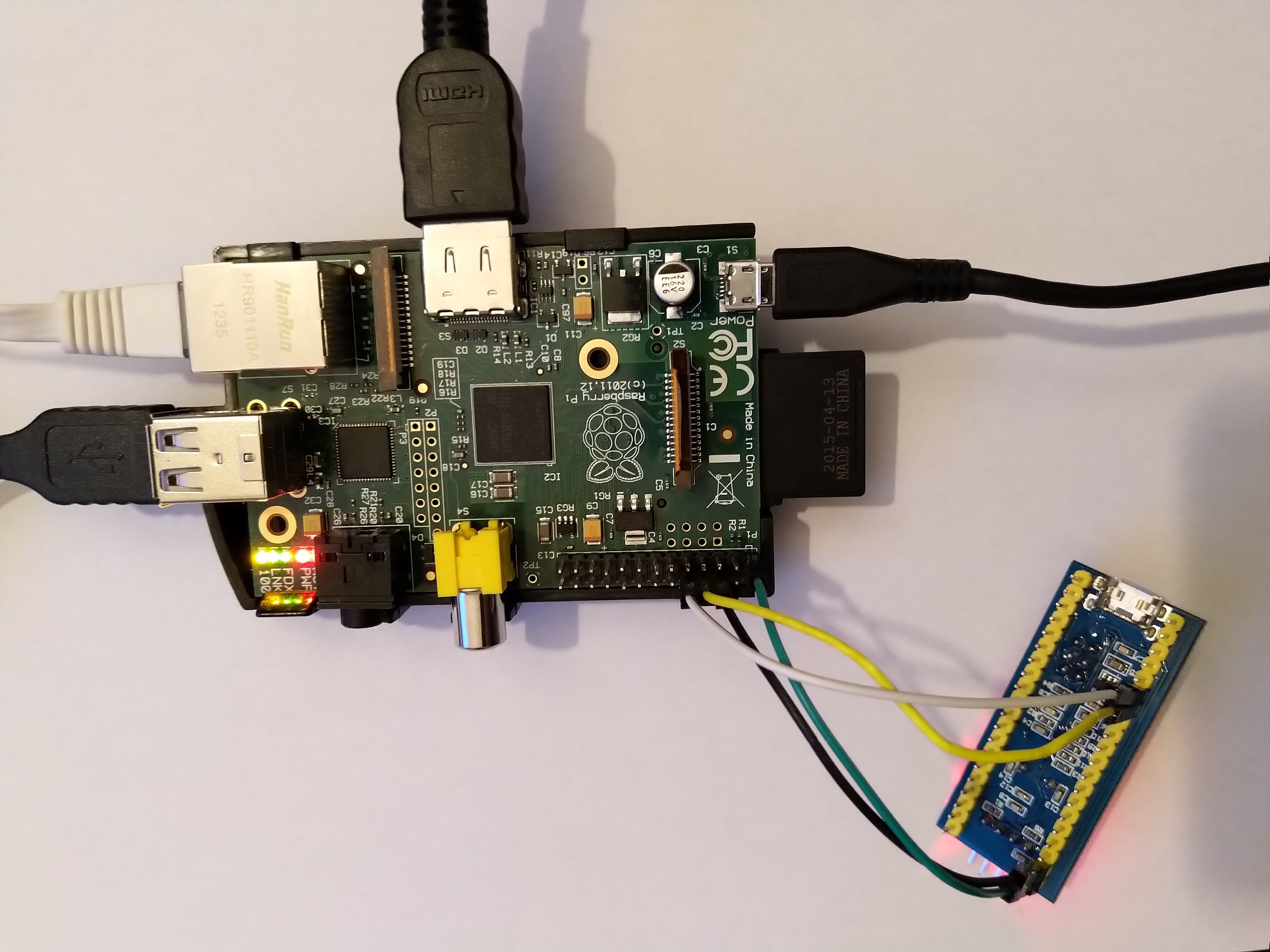
But I did have a Rasberry Pi and I knew that it had a TTL UART but had no idea how to use it to flash a Blue Pill. I did some research and quickly discovered that that Mathew Dunn had the same idea. He made a video and a blog post about it.
Unlike Mathew, I have the original Raspberry Pi model B, not a Raspberry Pi 3. My steps are adapted from his. The link to the boot bootloader in his post no longer works and I needed to reboot the Pi after disabling the serial console. These were the steps I followed:
Install the stm32flash utility
git clone https://git.code.sf.net/p/stm32flash/code stm32flash-code
make
sudo make install
Move the high performance UART from the Bluetooth device to the GPIO pins
This was not necessary on the original Raspberry Pi Model B but this step is detailed in Mathew Dunn’s blog post
Remove console from serial port
Edit cmdline.txt:
sudo nano /boot/cmdline.txt
Remove the following text in cmdline.txt to prevent a console from running on the serial port:
console=serial0,115200
Reboot the Raspberry Pi
Connect Raspberry to Blue Pill
| Raspberry Pi | Blue Pill |
|---|---|
| 3.3V (PIN 1) | 3.3V |
| GND (pin 6) | GND |
| TX (pin 8) | RX (pin A10) |
| RX (pin 10) | TX (pin A9) |

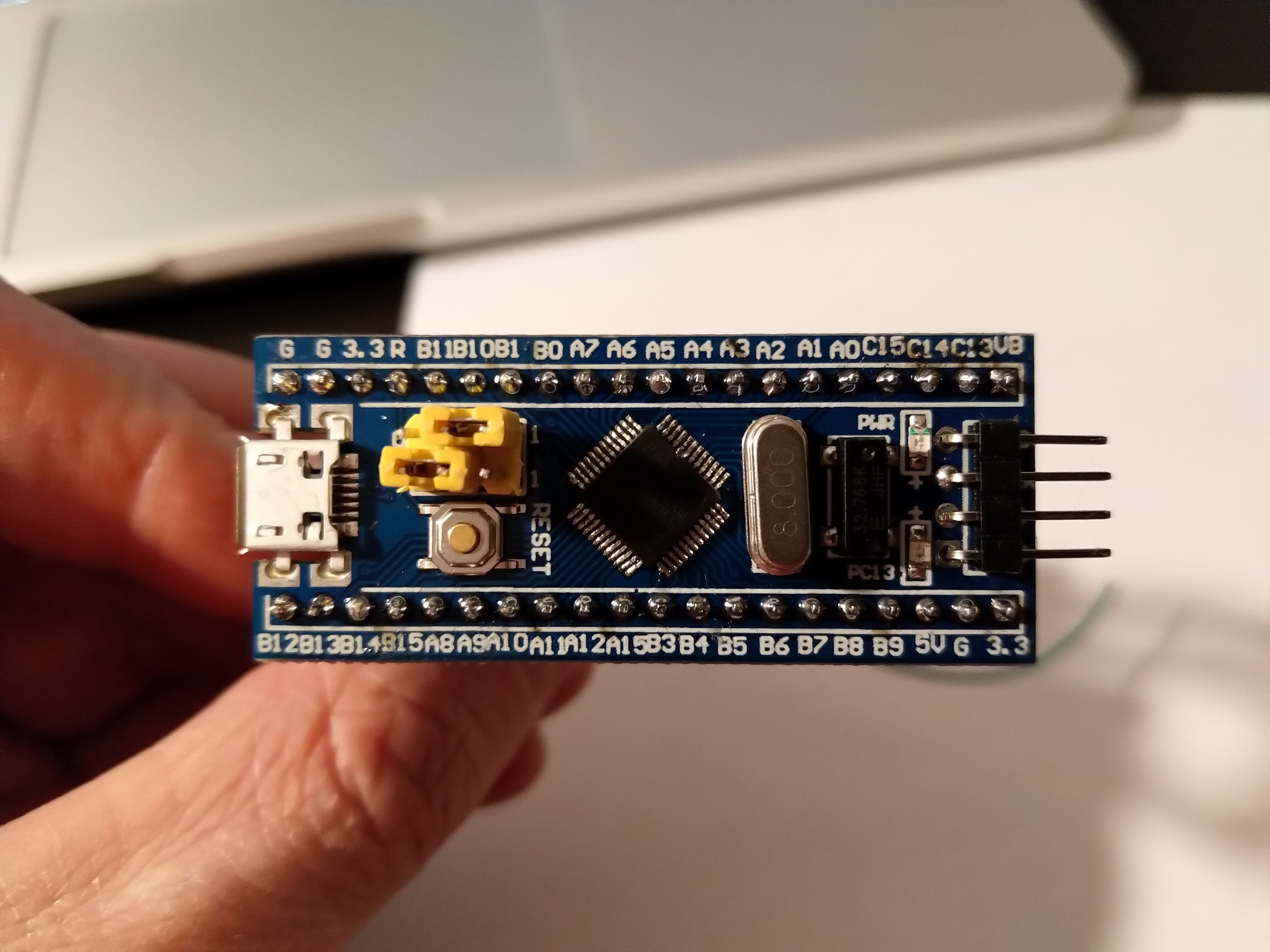
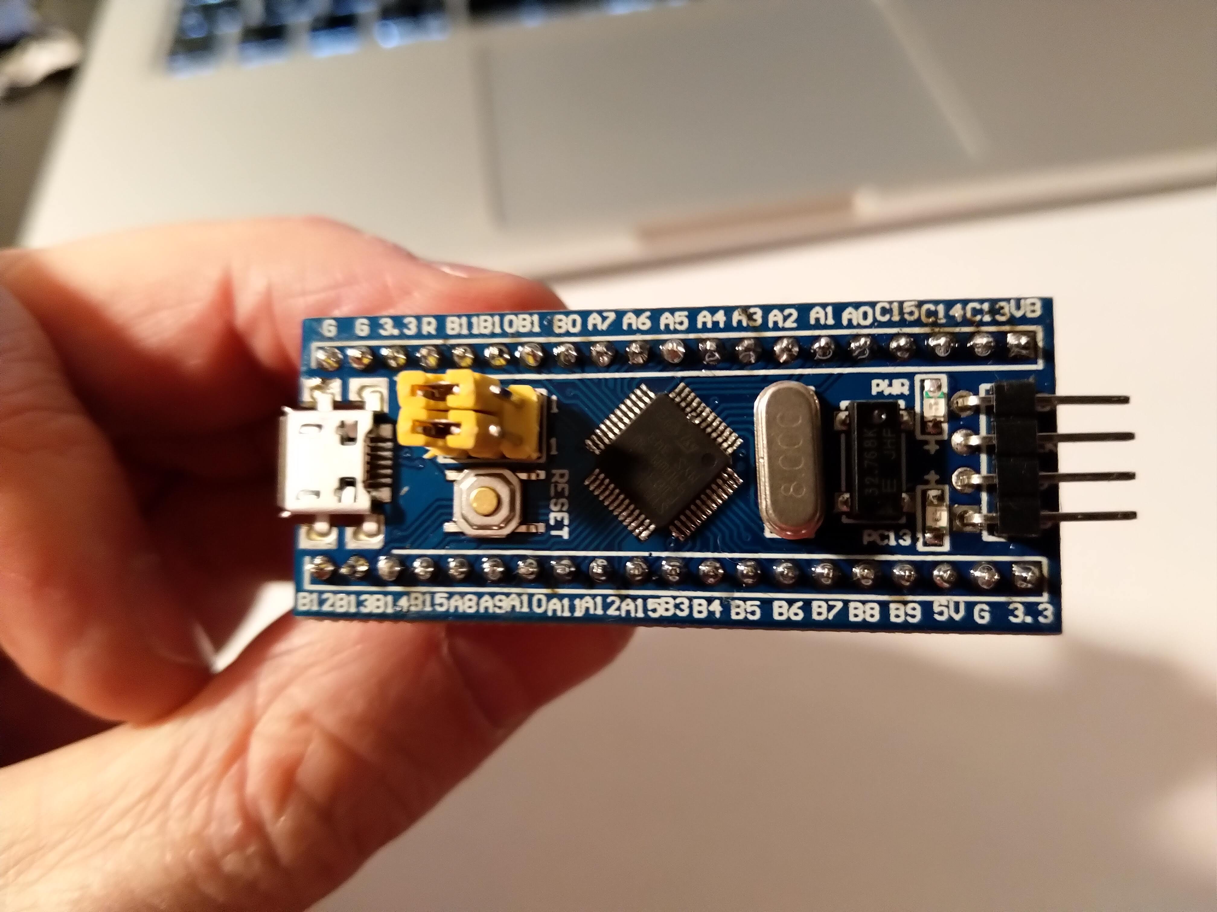
Set the STM32 BOOT0 jumper to 1:

Flashing a boot-loader
git clone https://github.com/rogerclarkmelbourne/STM32duino-bootloader
If you want to use the Arduino IDE you can use the image below, alternatively you could flash your own compiled binary directly to the micro-controller.
Press the RESET button on your micro controller before running stm32flash
stm32flash -v -w ./STM32duino-bootloader/bootloader_only_binaries/generic_boot20_pb12.bin /dev/serial0
Restore the jumpers to their original configuration.
Set the STM32 BOOT0 jumper to 1:

Credits
Thanks to Mathew Dunn for the original blog post.
Thanks to Roger Clarke for writing the bootloader.