Blue Pill Lora Transmitter Receiver with HopeRF module and Arduino IDE
Blue Pill Lora Transmitter Receiver with HopeRF module and Arduino IDE
I became interested in LoRa after watching Andreas Spiess’s LoRa / LoRaWAN Range World Record Attempt video.
I wondered if I could connect a LoRa module directly to a flight controller and use it to receive telemetry from a quadcopter or an RC plane.
Having no experience with LoRa, SPI or microcontrollers, I decided the best path forward would be to build something simple to test a LoRa modules. Using the Arduino IDE appeared to be the easiest way to get something working quickly. Arduino has a thriving community and lots of tutorials.
I used a STM32F103 “Blue Pill” board and a RFM95W module. The Blue Pill is not a typical Arduino board, it uses an STM32 microcontroller with some architectural similarities to the microcontrollers found in many flight controllers used in racing quads and RC planes.
Blue Pill tools setup
The Blue Pill does not have a USB bootloader installed out of the box. If you want to use a USB bootloader it has to be loaded using either ST-LINK or a TTL UART.
I did not have a ST-LINK V2 STM8 / STM32 Simulator Programmer clone or a working TTL UART serial converter e.g. Geekcreit® FT232RL FTDI USB To TTL Serial Converter Adapter Module For Arduin, so I used a Raspberry Pi to flash a USB bootloader to the Blue Pill.
The best “Hello world” introduction to the Blue Pill I found was Joop Brokking’s Getting started with the STM32 microcontroller - STM32F103C8T6 via Arduino.
After downloading and installing the Arduino IDE, I installed “Arduino SAM Boards (32-bit ARM Cortex-M3) by Arduino” version 1.6.11 from Tools -> Boards -> Boards Manager in the Arduino IDE.
I cloned the Roger Clark’s Arduino STM32 into the hardware directory of Arduino IDE:
E.g. on macOS, In a terminal:
cd /Applications/Arduino.app/Contents/Java/hardware
git clone git@github.com:rogerclarkmelbourne/Arduino_STM32.git
I was on commit 9a489ca25fa2794bd39d4d2d46e1d9d3ecd733e2
Hardware
Antenna
I used the 868 MHz version of the RFM95W module for use in the EU. I soldered an 86.5 mm trailing wire which I believe is appropriate for 868 MHz.

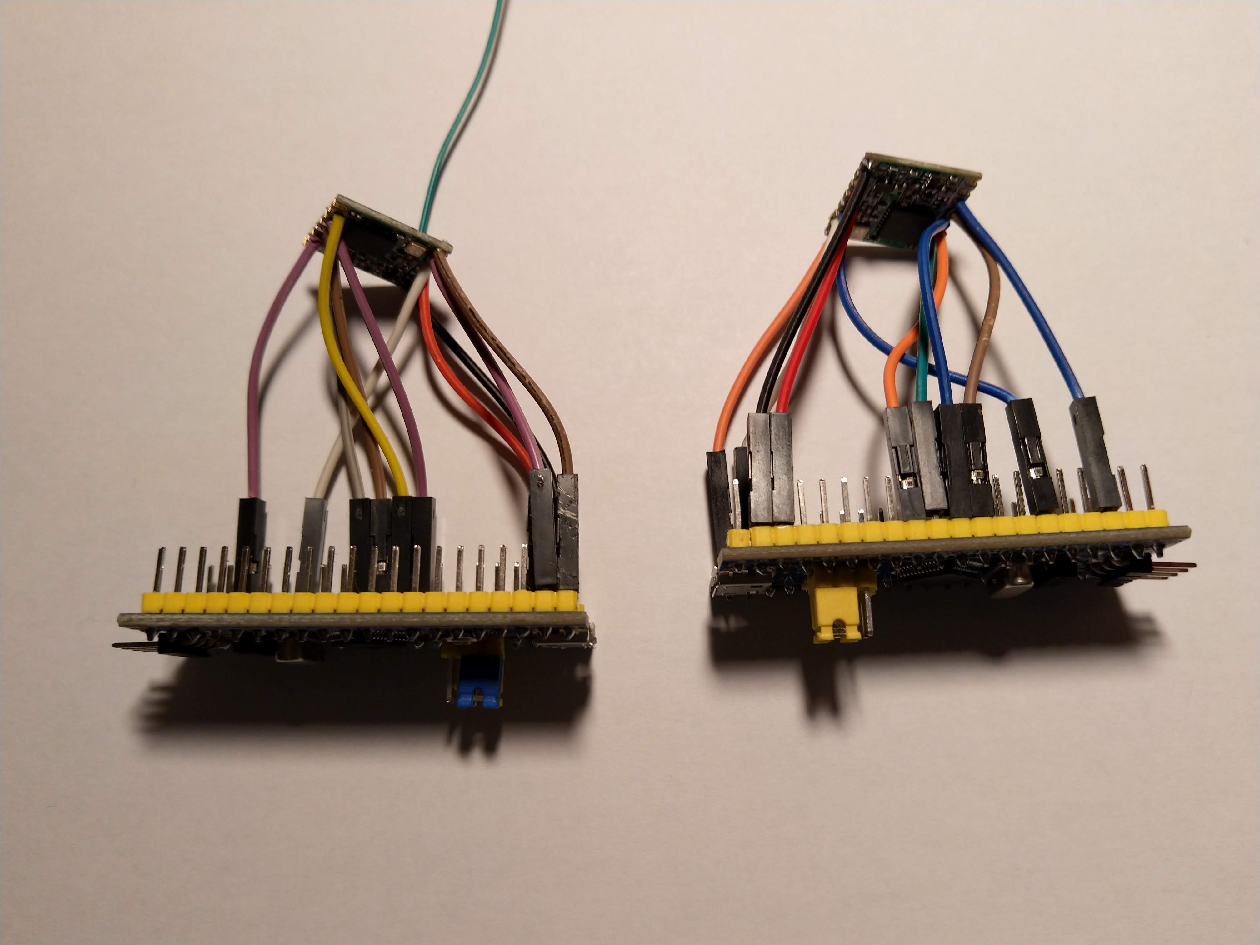
Wiring the HopeRF Module to the Blue Pill.
I soldered female jumper cables to the HopeRF RFM95W.
I connected to the HopeRF RFM95W to the Blue Pill as follows:
| HopeRF module | Blue Pill |
|---|---|
| VCC | 3.3V |
| GND | GND |
| SCK | PA5 |
| MISO | PA6 |
| MOSI | PA7 |
| NSS | PA4 |
| NRESET | PC14 |
| DIO0 | PA1 |
| DIO1 | PB13 |
| DIO2 | PB12 |
HopeRF modules connected to Blue Pills

Software
I used armtronix’s Modified lib of sandeepmistry arduino-LoRa for STM32F103. The documentation mentions only Semtech SX1276/77/78/79 not the HopeRF module.
I’m not sure how non-arduino blessed libraries are best imported into the Arduino IDE. I ended up doing “Sketch -> Add file” for LoRa_STM32.cpp and LoRa_STM32.h
In LoRa_STM32.cpp I changed #include <LoRa_STM32.h> to #include "LoRa_STM32.h" because LoRa_STM32.h was now part of the project not a library.
In LoRa_STM32.h, I changed #define LORA_DEFAULT_RESET_PIN PC13 to #define LORA_DEFAULT_RESET_PIN PC14 because on the Blue Pill, PC13 is connected to a LED that I’m using to indicate when a packet is sent or received.
The LoRa Transmitter
I made a transmitter application based on the example code. Instead of printing to the serial device, it flashes the LED when a packet is sent.
int counter = 0;

void setup() {
  pinMode(PC13, OUTPUT);
  LoRa.setSpreadingFactor(12);
  if (!LoRa.begin(868E6)) {
    while (1);
  }
}

void loop() {
  // send packet

  LoRa.beginPacket();
  LoRa.print("hello ");
  LoRa.print(counter);
  LoRa.endPacket();
  counter++;
  digitalWrite(PC13, LOW);
  delay(100);
  digitalWrite(PC13, HIGH);

  delay(5000);
}
The LoRa Receiver
I made a receiver application based on the example code. Instead of printing to the serial device, it flashes the LED twice when a packet is received. The double blink was useful since the transmitter and the receiver look identical.
#include <SPI.h>
#include "LoRa_STM32.h"

void setup() {
  pinMode(PC13, OUTPUT);

  LoRa.setSpreadingFactor(12);
  if (!LoRa.begin(868E6)) {
    while (1);
  }
}

void loop() {
  int packetSize = LoRa.parsePacket();
  if (packetSize) {
    while (LoRa.available()) {
      LoRa.read();
    }
    digitalWrite(PC13, LOW);
    delay(100);
    digitalWrite(PC13, HIGH);
    delay(100);
    digitalWrite(PC13, LOW);
    delay(100);
    digitalWrite(PC13, HIGH);
}